


A Preliminary Talk on Power Supply in Active-Clamp and Half Bridge Resonant (LLC) Circuit Design Reference I : Output Capacitor Design
Key considerations for designing the output capacitor of a switching power supply are mainly comprised of two items: 1. Ripple current tolerance (related to the equivalent series resistance (ESR) of a capacitor); 2. Load transient response (related to the capacitance of a capacitor). Basically, these are two key considerations when selecting output capacitor in circuit design. In the following contents, active-clamp and half-bridge resonant (LLC) output capacitor selection and the circuit differences will be shared.
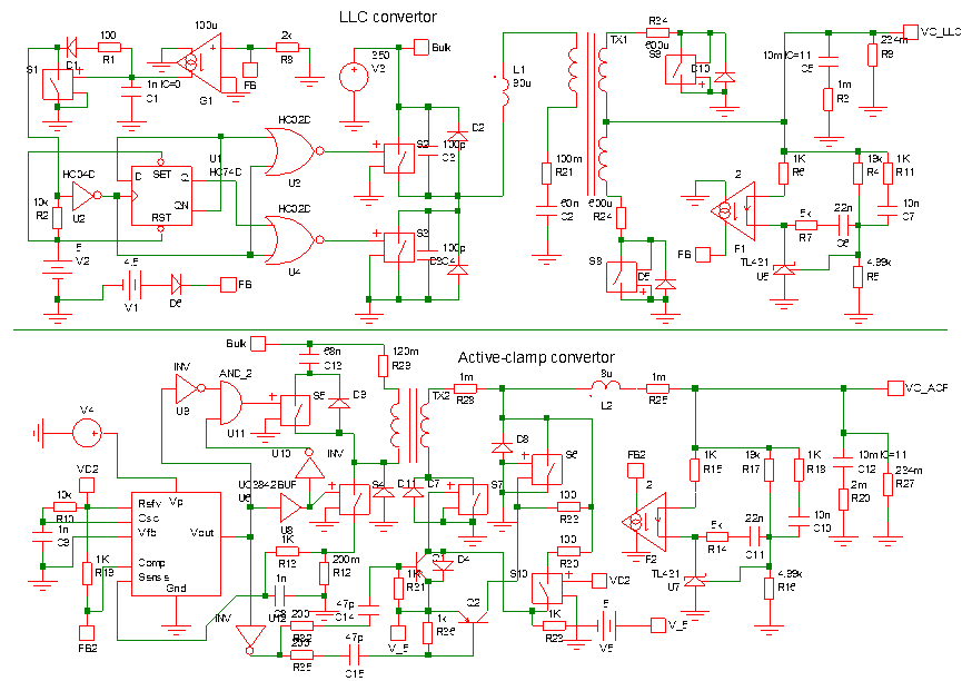
In this paper, scientific simulation software Simetrix was employed to carry out verification and comparison in order to objectively state the design considerations. For the modeling requirements, active-clamp and half-bridge resonant models should be constructed individually, and the models should include the complete circuit structure, supposedly composed of the primary-side controller (PWM), main switching element, transformer, resonance component, secondary-side rectification switching element, filter inductor, filter capacitor, and feedback unit. In order to simultaneously present the simulation results, an active-clamp model and a half-bridge resonant model were combined in a project, enabling them to perform simulated calculations. The design specification in this simulation was 12V(51.3A) 615W single output, as shown in the diagram below (upper half: LLC convertor; lower half: active-clamp convertor).
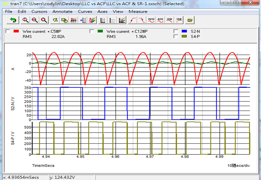
The simulation focused on the ripple current value of the output capacitor. With the loading condition set at “full load”, the ripple current values of C5 Capacitor (output capacitance of LLC) and C12 Capacitor (output capacitance of active-clamp) were measured. The measurement results are as shown in the waveform below. The current value of LLC (C5) was 22.82A, and the ripple current value of active-clamp (C12) was 1.96A, far lower than that of LLC.
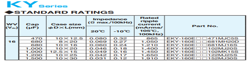
Subsequently, the two structures were matched with suitable capacitors. The active-clamp had a low ripple current value; therefore, a KY series 1500uF16V*2 electrolytic capacitor was selected, which met the requirement of ripple current derating at less than 1. The computed 1.96A/1.91A*2 =0.51 result was 0.51<1, and the 3000uF capacitor adequately satisfied response to load transients. Additionally, since the half-bridge resonant LLC had a very high ripple current value, a PSC solid series 470uF16V*4 electrolytic capacitor was selected, with the ripple current derating at less than 1. The computed 22.82/6.1*4=0.934 result was 0.934<1, and the 1880uF capacitor adequately satisfied response to load transients.
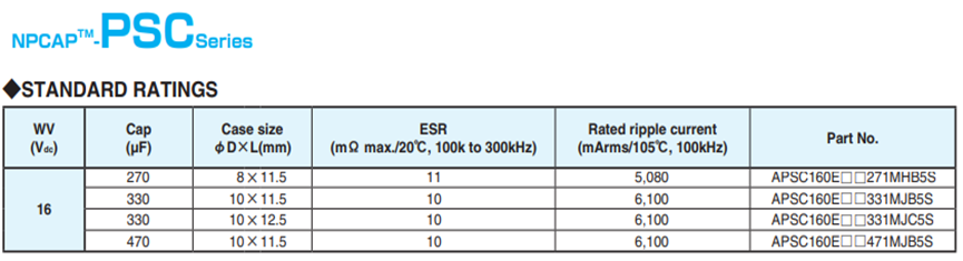
Based on the results of the above capacitor selection, the selection of multiple solid capacitors for the half-bridge resonant LLC structure proves to be an absolute necessity. As for the capacitor loss difference, active clamp loss is calculated as: =33mΩ*1.96^2=127mW (loss =63.5mW/each); half-bridge resonant LLC loss is calculated as: =(10mΩ/4)*22.82^2=1.3W(loss =325mW/each). From the perspective of capacitor loss, a half-bridge resonant LLC incurs higher loss.
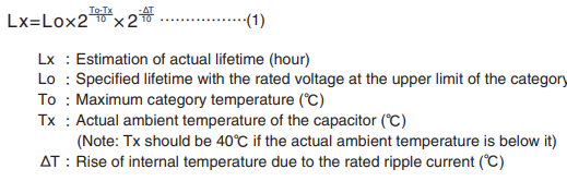
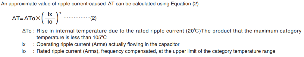
The capacitor lifetime and design were compared. In reference to the technical documents on Lifetime Estimation by Nippon Chemi-Con, it was found that the lifetime of solid capacitors and electrolytic capacitors followed the Arrhenius’s Law. With every 10°C increase, the lifetime decreased by half. The capacitor parameters were then substituted into the lifetime estimation equation to obtain the time value:
The lifetime of an active-clamp capacitor: KY capacitor lifetime 7kHr 105°C
Lx=7k*2(105°C-40°C)/10*2(20°C)*(-1.96/2/1.91/10)=311kHr
The lifetime of a half-bridge resonant (LLC) capacitor: PSC capacitor lifetime 15kHr 105°C
Lx=15k*2(105°C-40°C)/10*2(20°C)*(-22.82/4/6.1/10)=371Hr
The above calculation results show little difference between the lifetime of a half-bridge resonant (LLC) with a 15kHr solid capacitor and the lifetime of an active-clamp with a 7KHr electrolytic capacitor. Rumor has it that structurally, the lifetime of a half-bridge resonant (LLC) with a 15KHr solid capacitor is superior to that of an active clamp with an electrolytic capacitor.
Lifetime Estimation Equation:
Lifetime Estimation:
The infiltration rate of the oxygen is depend on the temperature as the liquid electrolyte evaporation and the relationship follows the Arrhenius's Law, too. Similarly, thermal degradation of the conductive polymer by self-heating follows the Arrhenius's Law, too. Therefore, the lifetime estimation has been using the theory of lifetime reducing by half at every 10℃ rise of the ambient temperature.
FSP Group has a complete lineup of power supply products. The active-clamp and half-bridge resonant (LLC) circuit design has been extensively applied in our product scope, and considerations for the output capacitor design are shared through objective reviews.
Related Articles


About FSP
FSP Group is one of the global leading power supply manufacturer. Since 1993, FSP Group has followed the management conception “service, profession, and innovation” to fulfill its responsibilities as a green energy resolution supplier.