


An Introduction on Circuit Design References of Active-Clamp and LLC Power Supplies III : Comparison of Bulk Cap Applications in Circuit Design
Normally, the switching PSUs inhere the Bulk Caps, it filter the ripple current of active power factor correction and also provides the necessary power energy during the Hold-up Time period. This thesis devotes two major parameters of Bulk Cap in studying PSU design, namely Hold-up Time and Ripple Current.
I. Power Supply Hold-up Time is relevant to the allowable work voltage of the PSU topology, for instance, with the same capacitance, the Hold-up Time of an Active-Clamp is much longer than that of Half-Bridge Resonance (LLC) due to their allowable work voltage being 385V~200V (Active-clamp) and 385V~310V (LLC) respectively. Next, estimation is made to find out the Bulk Cap difference of both designs under the same Hold-up Time condition.
Calculation is as follows:
Capacitance Energy Formula: J=C*(Vp2-Vv2)*T, energy in Joules J, capacitance in Farad C, Normal Voltage of Bulk Cap Vp, minimum holding voltage Vv, Hold-up Time T.
Substituting the respective parameters into Capacitance Energy Formulas and equaling between the both side may derive the ratio of Cacf : Cllc.
Cacf *(3582-2002)*T= Cllc*(3582-3102)*T, the derived ratio is Cacf =0.45Cllc #.
From the above calculation we learn that the capacitance of an Active-clamp is only 0.45 times that of Half-bridge Resonance (LLC). That is to say, 1 capacitor in an Active-clamp circuit may provide the same amount of Hold-up Time as would 2 capacitors in an LLC circuit.
II. Ripple Current: The Ripple Current of the Bulk Cap results from the summation of the current of the step-up reactor in the Active Power Factor Corrector and that of the load (e.g., the main switching current of the DC to DC Converter). A known technique is: via the leading edge-trailing edge approach, the current of the step-up reactor is made to be just passing the duty cycles of the main (DC to DC) switch, thereby reducing the Ripple Current of the Bulk Cap. However this approach only applies to controllers with a fixed frequency, such as an Active-clamp Controller. It is not applicable to half-bridge resonance (LLC) inverters. Since the Ripple Current of a Bulk Cap cannot be fully expressed using simple mathematic equations, therefore the Simetrix simulation tool became an effective way to obtaining the ripple current value, by simulating models that established an active power factor correction with Active-clamp and a Half-bridge Resonance (LLC) respectively.
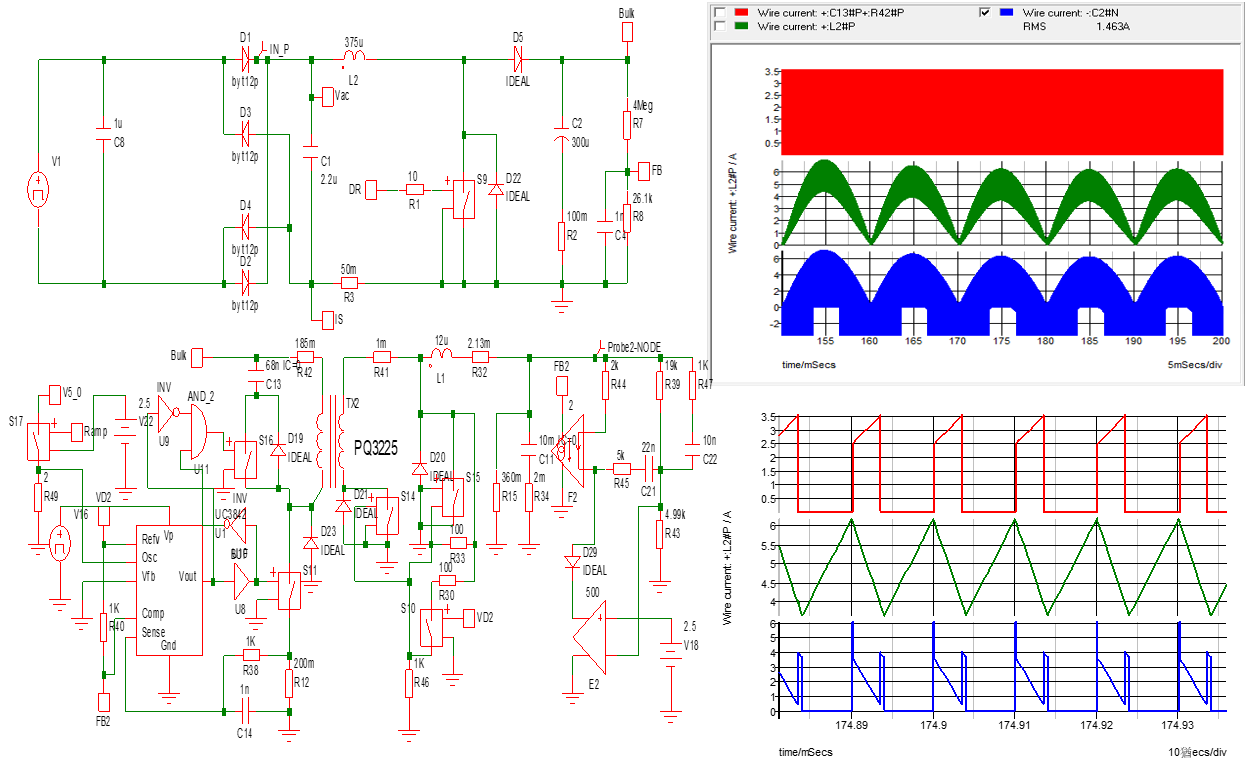
Simulation is then carried out under the conditions of 115Vac, 400W. Current readings are taken for the L2 Step-up Reactor, L3 resonance reactor, S11 Main Switch, and C2 Bulk Cap together with the measurement of C2 current (RMS). Fig.1 shows the simulation circuitry of the half-bridge resonance (LLC), waveform, and C2=2.23A. Due to lacking synchronization, the waveform of the C2 current is rather untidy (the blue portion on the upper right). Fig.2 shows the simulation circuitry of the Active-Clamp, waveform, and C2=1.463A. This C2 current wave form (the blue portion on the upper right) is much tidier due to the existence of synchronization. From the simulation results, the Bulk Cap currents are respectively 2.23A and 1.463A, a ratio of 1.52, better with the Active-clamp. But from the losses wise, the Bulk Cap Energy Loss, P=I2*ESR, the true difference should be (1.522=2.31) times.
Summarizing the above calculations and simulations, using 1 Bulk Cap in an Active-clamp configuration is better than using 2 Bulk Caps in a half-bridge resonance (LLC) configuration. Furthermore, the Hold-up Time Cacf =0.45Cllc,LLC with two capacitors 0.45*2=0.9 is still less than 1, this means Active-clamp better and also the energy loss of the Bulk Cap, P=2.31*0.5 (2 capacitors in parallel) =1.16, also gives a higher loss.
Fig.1 Half-Bridge Resonance (LLC), the Lower Left shows the simulation circuit, the Upper Right shows the full range wave form and RMS=2.23A, and the Lower Right shows the zoom-in image of the area.
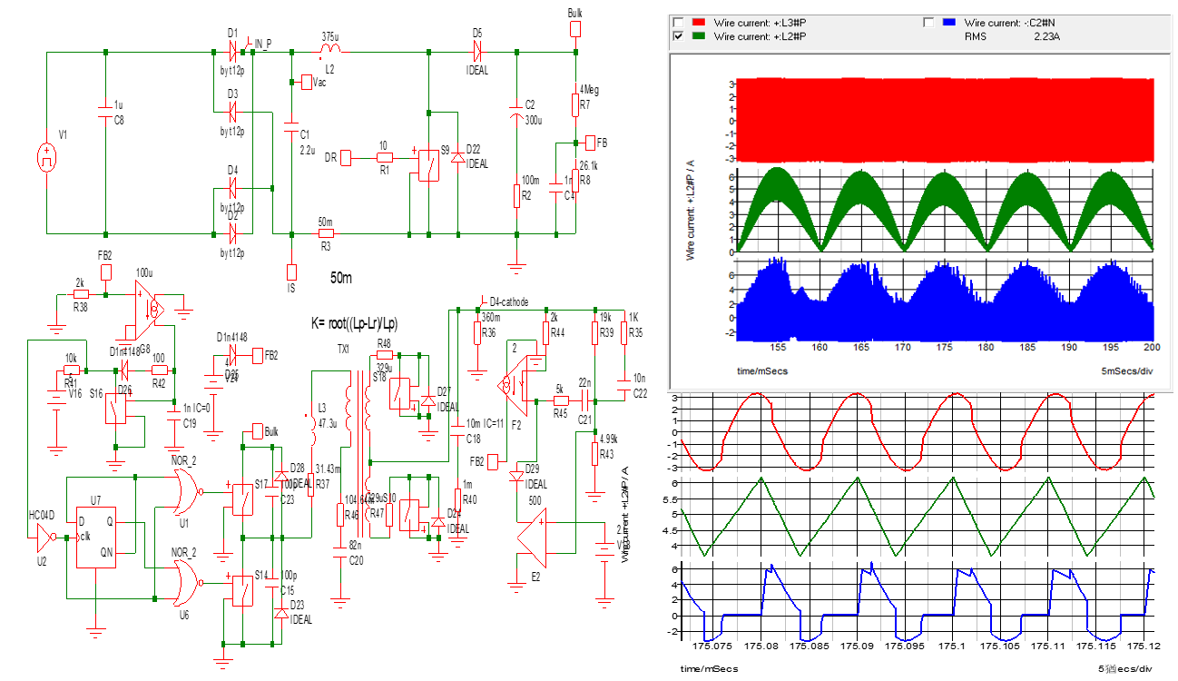
Fig.2 Active Clamp, the Lower Left shows the simulation circuit, the Upper Right shows the full range wave form and RMS=1.463A, and the Lower Right shows the zoom-in image of the area.
FSP Group offers comprehensive Power Supply product lines. Circuits configured in Active-clamp and Half-Bridge Resonance (LLC) are widely used in our scope of products. Objective comments are shared for the considerations in a Bulk Cap Design.
Related Articles


About FSP
FSP Group is one of the global leading power supply manufacturer. Since 1993, FSP Group has followed the management conception “service, profession, and innovation” to fulfill its responsibilities as a green energy resolution supplier.